⚡ Welcome to Substation Blog — Your resource for electrical engineering, safety & substation technology. About Us

Wednesday, 10 January 2018

Substation grounding details

 •   •  No comments
360TotalSecurity.com INT
SPONSOR

Substation Grounding

The grounding connections provided to substation equipment and structures fall under two categories, namely
a. Safety Grounds
b. System Grounds
System ground is normally for neutral grounding and safety ground is for equipment grounding. Minimum conductor size for equipment safety grounding.
All safety ground termination shall be made directly on to the ground grid. All system ground shall be terminated on to a ground rod interconnected to the grounding grid.

SOIL RESISTIVITY MEASUREMENT

Measurement

·      A number of measuring techniques are described in detail in ANSI/IEEE 8. The Wenner's four-pin method as described in ANSI/IEEE 8shall be used for measurement of soil resistivity. As many readings as required for various spacing and depth, in all the eight directions, sufficient to model the soil shall be carried out.
·      Soil resistivity readings shall normally be taken under dry conditions, during Summer months, if possible, However the same shall not affect the project’s schedule.
·      Fill up soil resistivity shall be carried by soil modeling in laboratories on samples dried to 2% moisture content after compaction.
·      Soil resistivity measurement shall also be carried out before and after fill up and compaction of soil at site.

Interpretation of Test Results

For soils with resistivity value less than 500 Ohm, if the difference between the highest and the lowest readings are within 30 % then the soil can be considered as uniform soil. For soils with resistivity value greater than 500 Ohm, if the difference between the highest and the lowest readings are within 20 % then the soil can be considered as uniform soil. For uniform soils, the mean value shall be considered as soil resistivity value. In case of wide variations in field readings, computer software alone shall be used to simulate two-layer model or multi-layer soil model. Two-layer soil models are good approximation of many soil structures, while multi-layer soil models may be used for more complex soil conditions. Software shall be based on IEEE-80.


Backfill Material

Backfill material shall have possibly the same soil resistivity or better than that of the original soil. In case of considerable backfill the soil resistivity shall be taken after completion of the backfill compaction. The same shall be used for grounding calculations. In case of delay of backfill activity at site the estimated value of resistivity of the backfill material or that of the existing soil whichever is higher shall be used for grounding calculations.

SELECTION OF GROUNDING CONDUCTOR MATERIAL, SIZE AND JOINTS

Basic Requirements


  • ·           Copper material shall be used for grounding.
  • ·           Soft drawn, stranded copper shall be used for the ground grid conductors.
  • ·           The conductor shall be round shaped for maximum cross-sectional contact with the ground. In coastal zone with low soil resistivity, tinned copper conductor shall be used. Copper-clad steel shall be used for ground rods.
  • ·    Each element of the ground system (including grid proper, connecting ground leads, and electrodes) shall be so designed that it shall :
  • ·       Resist fusing and deterioration of electric joints under the most adverse combination of fault-current magnitude and fault duration to which it might be subjected.
  • ·           Be mechanically rugged to a high degree, especially in locations exposed to physical damage.
  • ·     Have sufficient conductivity so that it will not contribute substantially to dangerous local potential differences.

Equipment grounding details

Steel Structures and Switch Racks

Switch racks and every steel structure that supports insulators or electrical equipment shall be grounded by means of bolted connections at two (2) diagonally opposite legs. Equipment mounted on steel supporting structures shall have separate grounding conductors. The pigtail ground conductor shall be supported on the structure at 1.0 meter intervals by clamps. Casting pigtail conductor inside the steel structure concrete foundation is not acceptable.

Fences / Gates

If space permits a perimeter ground conductor shall be laid which follows the
fence line and the gate in any position (open or close) and the fence then shall be bonded electrically at corner posts, gate posts and every alternate line post. The gates shall be bonded to the gateposts with a flexible copper cable or braid.
The barbed wire on the top of the SSD (Safety and Security Directive) type
fence/boundary wall, if applicable, shall be bonded to the grounding grid.

Cables

Metallic cable sheaths shall be effectively grounded by connecting a flexible braid to the sheath to eliminate dangerous induced voltages to ground.

Control Cables

Metallic sheath of control cables shall be grounded at both ends to the grounding grid via ground busbar in the cubicle.

Power Cables

a. Sheath of Power cables rated 69kV to 380kV shall be grounded directly from one end and through SVL(Sheath Voltage Limiters) from the other
b. Grounding of sheath of single core cables rated for 34.5kV and 13.8kV shall be from One end only.
c. Sheath of three core cables rated for 13.8kV shall be grounded at both ends.

 If ring type CTs are installed on power cables, the grounding of sheath shall be done such that the sheath current to ground will not influence CT secondary current.

Instrument Cables

Instrument cables carrying analog or digital signals shall have their metallic screening grounded at one point by means of PVC insulated grounding wire connected to separate instrument ground bar which is insulated from cubicle ground.

Signal Cables

All signal cables used in telemetering and communications shall have their shield grounded at one end only to reduce interference from stray sources.

Cable Tray System

Cable tray system shall be grounded with bare copper conductor of 50mm² size at
both ends and shall be bonded across gaps including expansion gaps

Substation Buildings

Substation buildings shall be encircled by a grounding conductor.
Reinforcement bars of the substation buildings and equipment foundation in the yard shall be connected to the main grounding grid at least at two diagonally opposite points.
For grounding of the electrical apparatus installed inside substation
buildings two separate exposed copper conductors/strips of size per manufacturer recommendation, each connected to the grounding grid at two (2) different points shall be laid. The grounding grid shall be laid inside the substation buildings and
it shall be connected to the main grid outside the buildings, at minimum two points.

Metal building(s)

·         Metal buildings shall be grounded at each substructure column with a minimum size of l20mm² bare copper conductor.
·         Angle irons installed on indoor trenches to support the metallic covers shall also be grounded at both ends.
·         Metallic doors in substation buildings shall be grounded with a flexible copper cable or braid.

HVAC

All air conditioning ducts inside the control building(s) shall be grounded at both ends and cross bonded at all joints and across the non-metallic duct connecting Air Handling Unit (AHU).
Grounding of control panels, Operating Mechanism Housing, Box, etc and other equipments associated with HVAC shall be done

Metallic Conduits

All metallic conduits shall be connected to the grounding grid at each manhole or at terminating points by using a conductor size of 50 mm². Conduits terminating in metal junction boxes shall be grounded by means of grounding studs or brazed connections. Where several conduits or junction boxes are located adjacent to each other, an adequately sized solid wire shall be used to interconnect the boxes. It shall be connected to grounding system at one single point.

Circuit Breakers and Disconnect Switches

·         All circuit breakers and disconnect switches shall be grounded at two diagonally opposite corners from two separate points of the grounding grid. Further  grounding switch blades of Disconnect Switch shall be directly grounded to grounding grid.
·         Good electrical connection shall be maintained between the steel structure and any bolted accessories mounted on it.
·         Operating Handles for Outdoor Switches as a large percentage of fatal accidents from voltage gradients are associated with manual operating handles of disconnect switches, etc.
·         A metal grounding plate or mat (operating platform), shall be placed where the operator must stand on it to operate the device. The operating handles shall be grounded by connecting a ground conductor (preferably flexible wire, braid strap) from the vertical operating pipe to the supporting structure, then continuing another stranded ground conductor to the switch operating platform. It is reiterated that the operating handle and the platform shall not be directly connected to the grounding grid but instead both connected to the support structure which in turn shall be connected to the grounding grid at least at two diagonally opposite points.

Terminal Transmission Tower Grounding

Terminal transmission towers located adjacent to the substation shall be connected to
the substation grounding grid at two diagonally opposite points. The shield wire shall
be connected to the tower structure, which in turn is connected to the grounding grid.

 Lightning Masts

Metal lightning masts shall have one safety ground.

Ring Main Unit (RMU)

The RMU inside the substation, if applicable, shall have two safety ground connections.

Oil Tanks and Oil /Water Pipings

All oil tanks shall be grounded at two points with bolted cable connections to two
different points of the grounding grid. Oil piping shall be grounded at intervals of
12m. Runs shorter than l2m shall be grounded at least at two points. Water piping
shall be connected to the grounding system at all service points. In addition, two
copper conductors of adequate size, shall be connected to the main water pipe from two separate points of the grounding grid.

Metal Clad Switchgear

Metal Clad switchgear shall have two safety grounds connected to the switchgear grounding bus. Withdrawable circuit breakers and PTs shall be provided with reliable connection to the ground bus. Grounding via the roller wheels and the rail is not acceptable.

Grounding of Lighting Equipment

Grounding of the lighting fixtures, lamp holders, lamps, receptacles and metal poles supporting lighting fixtures shall be per Article 250 and 410 of NEC (NFPA 70).

Portable Equipment

Portable electrical equipment shall be grounded in accordance with the
applicable requirements of Articles 250 of the NEC (NFPA 70).

Temporary Grounding

All the components used for temporary protective system shall meet IEEE Std. 1246,
“Guide for Temporary Protective Grounding System Used in Substations”.

Instruments, Relays and Meters

Instruments, meters and relays shall be grounded in accordance with the requirements of the NEC, Articles 250-120 to 126 and Articles 170 to 178.

Equipment Requiring both Safety and System Grounds

All operating grounds shall have their connections made to the grounding rods, which in turn shall be connected to the grounding grid.

Power Transformers

·         Power transformer tanks shall be safety grounded at two points diagonally opposite to each other. These connections shall be made from two different points of the grounding grid.
·         A separate system ground shall be provided for the neutral of the transformer by means of two (2) stranded copper wires. The neutral copper wire shall be sized for the system fault level.
·         The neutral grounding wires shall be insulated from the transformer tank by support insulators mounted on the tank wall and shall be connected to the grounding grid directly.
·         Independently mounted radiator bank and LPOF/XLPE cable termination
·         boxes shall be separately grounded at two diagonally opposite locations.
·         Tertiary windings and stabilizing windings shall be grounded per IEC60076-3, Annexure B.

Instrument Transformers

·         Potential and current transformers shall have their metal cases grounded.
·         The grounding terminal of the potential transformers shall be connected to the grounding grid.
·         The neutral point of the secondary connections of potential and current transformers shall be grounded to the ground grid in the control/relay room instead of switchyard to reduce the transient overvoltages.
·         Other requirements of instruments transformer grounding shall be per IEEE C57.13.3, “Guide for Grounding of Instrument Transformer Secondary Circuits and Cases”.

Surge Arresters

·         Where surge counter and/leakage current indicating meters are installed, a 5 kV insulated cable shall be used between arrester ground terminal and surge counter. The surge monitor's ground terminal shall be connected to the ground grid via two (2) 240 mm² stranded copper conductors.
·         The system ground conductor shall be as short as possible, free of sharp bends, and shall not be installed in metallic conduit. In addition, ground rods shall be driven adjacent to the arrester connection to the grounding grid to provide the lowest ground grid resistance at this point.

Station Auxiliary Transformer

Station auxiliary transformer shall be safety grounded at two locations diagonally opposite. One system ground shall be directly connected to the neutral wye connected windings that are to be solidly grounded.

Shunt Capacitors

Shunt capacitors are considered safety grounded when mounted on a metal structure
that is connected to the grounding grid. One system ground conductor shall be connected to the grounding grid when the capacitors are to be connected in a grounded star configuration.

Coupling Capacitor Voltage Transformers (CCVTs)

The grounding terminal and neutral point of secondary connections of CCVT shall be connected to the grounding grid similar to potential transformer as


Tuesday, 9 January 2018

Routine maintenance and inspection for power transformers

 •   •  No comments
360TotalSecurity.com INT
SPONSOR

Safety Precautions
  • A work permit must be issued and the qualified maintenance staff should carry the suitable safety category, 
  • Safety fence (rope) with caution marks surrounding the work area,
  • Transformer isolation and proper grounding is rquired
  • Wear your safety helmet
Tools and Equipment
  • Complete tool set
  • Digital DC voltmeter
  • Blower or vacuume cleaner
  • PVC ladder, brushes, megger 5000v/9000 vdc
Work to be Carried Out
  1. Check oil leaks,
  2. Check oil level in main tank, and bushings,
  3. Read and record the max oil temperature,
  4. Read and record the max winding temperature,
  5. Check all cooling fans for correct operation, and unusual noises,
  6. Check the transformer control cabinet for door seal, clean by blower with moderate pressure.
  7. Check the tap changer control cabinet ( if any ) for door seal, clean by blower with moderate pressure.
  8. Check the Silicagel breather,
  9. Clean all porcelain surfaces of all bushings insulators,
  10. Clean the neutral current transformer,
  11. Clean the neutral earth disconnect switch blades,
  12. Lubricate the neutral earth disconnected switch bearing points,
  13. Check all bolted connections for tightness,
  14. Measure the insulation resistance for each winding to ground to other winding and for core to ground
  15. Measure the winding turns ratio. R60/R15 > 1.2   every year 
  16. Measure the winding resistance using megger 5000/9000 Vdc  every year
  17. Check the pressure relief device,
  18. Check the temperature gauges indicator,
  19. Check all protection devices,
  20. Read and record the leakage current monitor test on the lightening arrestor,
  21. Check the Deluge system, transformer protection by water spray.
  22. Measure the insulation oil breakdown voltage test.     every year.
  23. Operate the tap changer from up to down off load (in case of step down transformer) and change the oil every year in case of  the transformer works at full load and every 2 years if at half load.
  24. Check the gas in the oil and treatment if necessary taking an oil sample 
  25. As required perform Power Transformer tests
Maintenance Record Data Sheet

Works to be Carried out
Test Result
Any oil leaks (if yes give location)Yes        No
Oil level in main tankOK       low      add
Oil level in bushings OK       low      add
Max oil temperatureoC
Max winding temperatureoC
All cooling fans operational (if "on" indicate no. of fan)Yes    No
Cooling fans noise (if "yes" indicate no. of fan)Yes    No
Transformer control cabinet cleaned and inspectedOK
Tap changer control cabinet cleaned and inspectedOK
Silicagel breatherOK            Change
All porcelain surfaces of all bushings insulators cleanedOK
Neutral earth disconnect switch blades cleanedOK
Neutral earth disconnected switch bearing points lubricatedOK
Neutral CT cleanedOK
All bolted connections checked for tightnessOK
Insulating oil breakdown voltage test  average kv   every year
            kv,  air gap       mm
Turns ratio value for winding   R60/R15 > 1.2   every year
OK            Not
Winding resistance using megger 5000/9000 Vdc  every yearOK            Not
Pressure relief device,OK            Not
Temperature gauges indicatorOK            Not
Record the leakage current monitor test on the lightening arrestor
(Deluge system) transformer protection by water sprayYes       No
Check the tap changer (if any in case of step down transformer) and change the oil                                   every yearOK            Not
Take oil sample for gas analysis and treatment if necessary
OK            Not

Power transformers routine inspection and tests (1)

 •   •  No comments

Safety Precaution 

  • A work permit must be issued and the qualified maintenance staff should carry the suitable safety category,
  • Wear your safety helmet and safety harnesses.
  • Transformer isolation and earthing on all its sides is required
  • There is a danger of falling into the oil containment pit when working near large power transformers.
  • A proper well fixed ladder should be used for climbing on top of the transformer tank.
Tools and Equipment
  • Safety helmet, safety belt, and tool set
  • Voltage indicator, Ladder
  • Portable earth for discharging,
  • Fine cloth for cleaning purposes, Silicagel,
  • Complete tool kit/set, including a torque wrench.
Environmental Recommendation
  • Before starting the cleaning of all porcelain surfaces of all transformer wear your breathing mask to protect lung tissues from the dust particulate.
  • Don't burn the cloth used in cleaning, collect it and send it to the dump.
  • Fix any oil leaks to prevent pollution and save money of wasted oil.
  • Oil leaks to the ground have very bad impact on the environment, mainly on soil and ground water and eventually on the ecosystem. "It takes only I liter of hydrocarbon spilled in an aquifer to render 1,000,000 liters of potable water useless for human consumption.
Work to be carried out
  1. Check  for signs of oil leaks, correct if possible.
  2. Inspect all painted surfaces of the transformer, remove any signs of rust and repaint bare spots 
  3. Check condition of earthing bus, all bolted connections must be checked for tightness. Thoroughly Clean all porcelain surfaces on all bushings.
  4. Check for correct oil level in all transformer bushings, top up if necessary.
  5. Open bleed valve on buchholz relay until a small amount of oil escapes, test alarm and trip circuit using the test button next to the vent, valve, check all electrical connections for tightness for tightness.
  6. Check the breather, if required replace or regenerate the silicagel.
  7. Check the pressure Relieve device on main transformer tank and if fitted on ULTC compartment.
  8. Inspect condition of all cooling fans, check that screens have no obstructions, check for cracks in fan blades, test run all motors and check for abnormal bearing noise. It is recommended to change motor bearings after 3000 hours of running time or every 4 years, whichever comes first.
  9. Interval may be adjusted by technical services unit.
  10. Inspect transformer control cabinet, blow out dust, check condition of door seal, check all electrical connections for tightness, check proper operation of space heaters.
  11. Use water pressure to clean radiators and transformer tank walls, do not direct the stream of water directly at the cooling fans. It is recommended to use the transformer deluge system to perform the cleaning operation, it will provide a functioning test for the system at the same time the unsealed wiring must be covered by plastic cover to avoid short circuit in wiring system.
  12. Take and record insulation resistance readings (Megger readings), high voltage winding to low voltage winding, high voltage to tertiary winding , low voltage to tertiary winding, high voltage to earth, low voltage to earth, tertiary winding to earth, Compare readings to historical data.
  13. Take and record capacitance and dissipation factor      %, Compare reading to historical data.
  14. Perform ratio tests in lowest, highest and neutral tap position, compare each high voltage to neutral winding to corresponding low voltage to neutral winding, reading taken at all points of tap changer. Compare readings to historical data
  15. Take and record winding resistance readings, each high voltage phase to neutral, Each low voltage phase to neutral, tertiary delta winding phase to phase Reading taken at all points of Tap changer, Compare reading to historical data
  16. Inspect and clean tap changer control cabinet, check all electrical connections for tightness, check functioning of cabinet heater and check door seals, check motor operating mechanism
  17. It is important to perform a complete tap changer (electrical operation) from highest to lowest step and back to the position it was found in, this action will clean all internal contacts of the tap changer
  18. Inspect condition of external tap changer drive shaft, tighten all couplings and bolted connections
  19. Take and record final reading on tap changer operations counter
  20. Take oil samples for laboratory analysis
  21. Be sure that all tools have been taken off the transformer
  22. Clean and apply Graphite Grease to all contact surfaces of all neutral disconnect switches, lubricate all bearing points
  23. Check for correct spacing of are horns on all bushings
  24. Clean, grease and tighten all couplings of drive shaft to neutral disconnect switches
  25. Place transformer back into normal operating condition

Substation Audit works

 •   •  No comments
Work to be carried out

Station Emergency Equipment
  1. Check for correct Location of fire extinguishers, check condition of extinguishers (fully charged and in good working condition, validity of expiry date)
  2. Check for availability of first aid kit, check content and replace as necessary.
  3. Test all emergency generators if on site, fuel tank should be at least 3/4 full.
Lighting
  1. Check all normal lighting fixtures, replace burnt out light bulbs or fluorescent tubes,
  2. Test all emergency DC light fixtures, replace any burnt out light bulbs
Control Rooms – Relay Rooms
  1. Dust off control and relay panels
  2. Check device indicating light, replace as required
  3. Check relay targets, report any relay flags to Protection Engineer

Portable Switching Equipment
  1. Check for portable earthling equipment- must be in good repair and properly stored.
  2. Check insulated switch sticks - be properly stored and in good condition, note date of last inspection.
  3. Inspect station ladders-must be in good repair and properly stored.
  4. Check safety barrier rope-there must be sufficient quantities and it must be properly stored
Housekeeping
  1. Check that all floors are properly cleaned and free of tripping hazards
  2. Check that all washrooms are clean and in good working order.
  3. Check that compressor room floor is clean and free of oil spills.
  4. Check that all windows are clean and in good working order 
General
  1. Check that all equipment is labeled probably  (names are written) according to the single line diagram
Indoor Switching Station
  1. Check for unusual noise and smells, exhaust and ventilation systems must be in good working order
  2. Check that all safety barriers are in place, all switching cell doors must be locked, all warning signs in place,
    all spare breakers and mobile service equipment (oil filtration unit, SF6 gas cart) must be properly stored
  3. Check control panels painting are in a good condition and cleaned.
Outdoor Switchyard
  1. Check that property fence is in good repair, check that all earth connections to fence and gates are secure and tight.
  2. Check all earth connections to all steel structures & equipment, tighten connections to station earth grid or earthing rods.
  3. Inspect gravel layer in yard, there must be no weeds, ensure there is no debris (plastic bags) present.
  4. Check that all warning signs in place to keep the public out
  5. Check that switched lighting is in working order, replace burnt out lights.
  6. Inspect condition of all porcelain bushings, report any contamination,
  7. Check for birds nest.
  8. Check for correct oil level in all oil filled bushings.
  9. Check disconnect and earthing switches, inspect for correct position of linkage in open or closed position.
  10. Check for condition of cable trenches, all covers must be in place.
  11. Check for condition of cable trenches, all covers must be in place.
  12. Inspect oil containment pits, must be clean and dry
  13. Check all equipment reinforced concrete foundations to see they are in good condition and there are no cracks.
  14. Check all the main transformer wheel brakes to ensure they are in the correct position.
  15. Check the condition of outside painting and ensure they are in a good condition and there is no rust

Replacing a Long Section of Damaged Conductor in transmission line

 •   •  No comments
Introduction
The purpose of this procedure is to provide detailed instructions on a safe method for replacing a Long section of Damaged Conductor.
Safety Precautions
  • Obtain a work permit.
  • Use approved fall protection equipment and procedures.
  • Use approved earthing equipment and procedures.
  • Calculate the weight of the conductor at the suspension point and the line tension of the conductor in order to select the proper tools required to complete the work procedure safely.
  • Before beginning any work, check for other energized circuits beside, below or in the vicinity of the conductor that you will lower to the ground.
Tools and Equipment
3 Handlines
1 Complete Fall Arrest Equipment, 1 Rope Ladder
1 Complete Temporary Earthing Equipment
1 Wire Rope Cable fitted with conductor clamps on both ends
1 Tirfor Hoist,
1 Bulldozer or Bulldozer Winch or Large Truck
3 Snatch Blocks, 1 Hydraulic Press and Dies
1 Nylon Sling, 2 Conductor Grips
4 Steel Slings, 6 Shackles
1 Ratchet Cutters, 1 Steel Conductor Brush
1 Aluminum Cutters / Trimmers
2 Aluminum Sleeves, 1 Measuring Ruler
1 Potential Indicator, 2 Steel Sleeves
2 Bandage Ties or Tape

Work to be Carried Out
  1. Obtain a work permit on both circuits of the tower that you will work on.
  2. Climb the towers, using approved fall protection, where temporary earths will be installed taking care to maintain the minimum limits of approach to the conductor.
  3. Install the hand-line on the tower and raise the potential indicator.
  4. Verify the isolation of both circuits on the tower.
  5. Install temporary working earths on the circuit that you will be working on at the locations as shown in (FIGURE # 1) to ensure that the conductor will be properly earthed on both sides of the work location tower.
Figure 1: TEMPORARY TOWER EARTH LOCATIONS
6.     Climb the work location tower using approved fall arrest procedures and install a handline in an appropriate position.
7.     Install a rope ladder at the end of the arm that suspends the damaged conductor.
8.     Install 3 snatch blocks at the following locations as shown in (Figure # 2)
# 1 at the tower leg nearest the footing and diagonal member.
# 2 on the tower shaft at the arm connection.
# 3 at the end of the tower arm directly above the suspension clamp.

Figure 2
9.     Install the wire rope cable through the snatch blocks as shown in Figure 2.
10. As one lineman holds the weight of the cable on the tower arm, another lineman descends the rope ladder and attaches the free end of the wire rope cable to the conductor by using a nylon sling and shackle as a choker.
11. Attach the other end of the wire rope cable to the bulldozer, bulldozer winch or heavy truck.
12. Take up tension on the wire rope cable by advancing the vehicle or the winch until the suspension insulators hang slack.
13. The lineman on the rope ladder then disconnects the suspension clamp from the bottom insulator or insulator rod.
14. The conductor is then lowered to the ground gradually.
NOTE: If the conductor that is being lowered must pass by another tower arm and conductor, a tag line should be attached to the conductor to pull it by the arm by applying horizontal tension until it is clear. Also note that if the conductor that is being lowered to the ground is any other than the bottom phase conductor that it may have to be lowered from two tower locations in order to reach the ground for repair. These procedures must be anticipated prior to installing the temporary earth locations.
15. Measure the distance of the damaged conductor and mark the cutting points with tape.
16. Measure and cut the new conductor section to the exact same length.
17. Install two conductor grips and the tirfor hoist on the conductor outside of the cutting marks by approximately two meters to allow for cleaning and sleeving.
18. Take up tension on the tirfor hoist until the damaged conductor section between the two grips becomes slack.
19. Before cutting the damaged conductor section, temporary earthing jumpers must be installed across the entire conductor section to ensure that no induced potential voltage or current arises between two open points.
20. Please refer to (FIGURE # 4) two alternative methods of applying an earthing jumper cable across this section. Depending on the length of the damaged section to be replaced, the choice of either method is acceptable.


21. After either earthing jumper method has been applied and checked for continuity, prepare to cut the damaged conductor by applying a tape bandage approximately 1.5 meters outside of the cutting marks to prevent the existing conductor from unraveling. Cut the damaged conductor at the cutting marks and remove the damaged section.
22. Slide the aluminum sleeve on both ends of the new conductor section.
23. Clean the aluminum strands of all 4 conductor ends with emery paper.
24. Measure and mark the distance to cut the aluminum strands to expose the steel strands by a distance equal to half the length of the steel sleeve plus 5 % of the entire steel sleeve length. This will allow for steel expansion while pressing. (See Figure 5A).

 
25. Wrap a tape bandage around both ends of the steel strands and slide the steel strands inside the steel sleeve. Remove the tape bandage and insert the steel strands fully into the steel sleeve until both conductor ends meet in the center of the sleeve. See (Figure 5 B


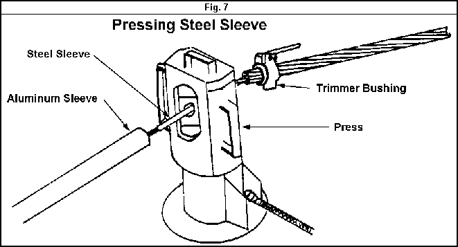
26. Using the hydraulic press, begin pressing the steel sleeve from the middle towards each end and overlap each press by 10 %. SEE (Figure 6) and (Figure 7)

.
27. Cover the pressed steel sleeve with a coating of conductive grease such as Penetrox to prevent corrosion
.


28. Measure the length of the aluminum sleeve and mark the conductor on both sides of the steel sleeve to ensure that the aluminum sleeve will be centered appropriately over the steel sleeve.
29. Slide the aluminum sleeve over the conductor to line up with each mark accordingly.
30. Using the hydraulic press, begin pressing the aluminum sleeve by centering the die over the filler hole and outward to the end of the aluminum sleeve. Overlap each press by 10 %

  
31. When the aluminum sleeve has been completely pressed, fill the sleeve cavity with conductive grease as shown in (FIGURE # 8).
32. Gradually release the tirfor hoist to transfer the tension to the new conductor line section.
33. Remove the tirfoe hoist and grip assembly.
34. Remove the temporary earth jumper or jumpers from the repaired conductor section.
35. Raise the repaired conductor section using the winch or vehicle.
36. Attach the suspension clamp to the insulator string.
37. Release the wire rope cable from the conductor and lower it to the ground on the hand-line.
38. Remove the snatch blocks and rope ladder and lower them to the ground on the hand-line.
39. Advise the crew that the temporary earths on the adjacent towers will be removed.
40. Remove the temporary earths on the adjacent towers and lower them to the ground on the hand-line.
41. Descend the towers using approved fall arrest and remove the fall arrest equipment from the towers.
42. Close the work permit.


Featured Post

The necessary response to substation problems

  When it comes to power distribution, substations are the backbone of our grid. Keeping them in optimal condition is essential to ensure re...

Popular Posts