Introduction
The purpose of this
procedure is to provide detailed instructions on a safe method for replacing a
Long section of Damaged Conductor.
Safety Precautions
- Obtain
a work permit.
- Use
approved fall protection equipment and procedures.
- Use
approved earthing equipment and procedures.
- Calculate
the weight of the conductor at the suspension point and the line tension
of the conductor in order to select the proper tools required to complete
the work procedure safely.
- Before
beginning any work, check for other energized circuits beside, below or in
the vicinity of the conductor that you will lower to the ground.
Tools and Equipment
3 Handlines
1 Complete Fall Arrest Equipment, 1 Rope Ladder
1 Complete Temporary Earthing Equipment
1 Wire Rope Cable fitted with conductor clamps on both ends
1 Tirfor Hoist,
1 Bulldozer or Bulldozer Winch or Large Truck
3 Snatch Blocks, 1 Hydraulic Press and Dies
1 Nylon Sling, 2 Conductor Grips
4 Steel Slings, 6 Shackles
1 Ratchet Cutters, 1 Steel Conductor Brush
1 Aluminum Cutters / Trimmers
2 Aluminum Sleeves, 1 Measuring Ruler
1 Potential Indicator, 2 Steel Sleeves
2 Bandage Ties or Tape
Work to be Carried Out
- Obtain a work permit on both circuits of the tower that
you will work on.
- Climb the towers, using approved fall protection, where
temporary earths will be installed taking care to maintain the minimum
limits of approach to the conductor.
- Install the hand-line on the tower and raise the
potential indicator.
- Verify the isolation of both circuits on the tower.
- Install temporary working earths on the circuit that
you will be working on at the locations as shown in (FIGURE # 1) to ensure
that the conductor will be properly earthed on both sides of the work
location tower.

Figure 1: TEMPORARY
TOWER EARTH LOCATIONS
6.
Climb the work location tower using approved fall arrest
procedures and install a handline in an appropriate position.
7. Install a rope ladder at
the end of the arm that suspends the damaged conductor.
8. Install 3 snatch blocks
at the following locations as shown in (Figure # 2)
# 1 at the tower leg
nearest the footing and diagonal member.
# 2 on the tower shaft
at the arm connection.
# 3 at the end of the
tower arm directly above the suspension clamp.

Figure 2
9. Install the wire rope
cable through the snatch blocks as shown in Figure 2.
10. As one lineman holds the
weight of the cable on the tower arm, another lineman descends the rope ladder
and attaches the free end of the wire rope cable to the conductor by using a
nylon sling and shackle as a choker.
11. Attach the other end of
the wire rope cable to the bulldozer, bulldozer winch or heavy truck.
12. Take up tension on the
wire rope cable by advancing the vehicle or the winch until the suspension
insulators hang slack.
13. The lineman on the rope
ladder then disconnects the suspension clamp from the bottom insulator or
insulator rod.
14. The conductor is then
lowered to the ground gradually.
NOTE: If the conductor
that is being lowered must pass by another tower arm and conductor, a tag line
should be attached to the conductor to pull it by the arm by applying
horizontal tension until it is clear. Also note that if the conductor that is
being lowered to the ground is any other than the bottom phase conductor that
it may have to be lowered from two tower locations in order to reach the ground
for repair. These procedures must be anticipated prior to installing the
temporary earth locations.
15. Measure the distance of
the damaged conductor and mark the cutting points with tape.
16. Measure and cut the new
conductor section to the exact same length.
17. Install two conductor
grips and the tirfor hoist on the conductor outside of the cutting marks by
approximately two meters to allow for cleaning and sleeving.
18. Take up tension on the
tirfor hoist until the damaged conductor section between the two grips becomes
slack.
19. Before cutting the
damaged conductor section, temporary earthing jumpers must be installed across
the entire conductor section to ensure that no induced potential voltage or
current arises between two open points.
20. Please refer to (FIGURE
# 4) two alternative methods of applying an earthing jumper cable
across this section. Depending on the length of the damaged section to be
replaced, the choice of either method is acceptable.


21. After either earthing
jumper method has been applied and checked for continuity, prepare to cut the
damaged conductor by applying a tape bandage approximately 1.5 meters outside
of the cutting marks to prevent the existing conductor from unraveling. Cut the
damaged conductor at the cutting marks and remove the damaged section.
22. Slide the aluminum
sleeve on both ends of the new conductor section.
23. Clean the aluminum
strands of all 4 conductor ends with emery paper.
24. Measure and mark the
distance to cut the aluminum strands to expose the steel strands by a distance
equal to half the length of the steel sleeve plus 5 % of the entire steel
sleeve length. This will allow for steel expansion while pressing. (See Figure
5A).


25.
Wrap a tape bandage around both ends of the steel strands and
slide the steel strands inside the steel sleeve. Remove the tape bandage and
insert the steel strands fully into the steel sleeve until both conductor ends
meet in the center of the sleeve. See (Figure 5 B
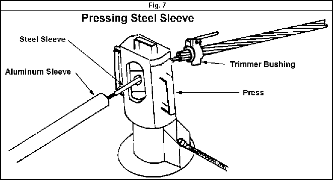
26. Using the hydraulic
press, begin pressing the steel sleeve from the middle towards each end and
overlap each press by 10 %. SEE (Figure 6) and (Figure 7)
.
.

27. Cover the pressed steel
sleeve with a coating of conductive grease such as Penetrox to prevent
corrosion
.
.
28. Measure the length of
the aluminum sleeve and mark the conductor on both sides of the steel sleeve to
ensure that the aluminum sleeve will be centered appropriately over the steel
sleeve.
29. Slide the aluminum
sleeve over the conductor to line up with each mark accordingly.
 30. Using the hydraulic
press, begin pressing the aluminum sleeve by centering the die over the filler
hole and outward to the end of the aluminum sleeve. Overlap each press by 10 %
30. Using the hydraulic
press, begin pressing the aluminum sleeve by centering the die over the filler
hole and outward to the end of the aluminum sleeve. Overlap each press by 10 %
31. When the aluminum sleeve
has been completely pressed, fill the sleeve cavity with conductive grease as
shown in (FIGURE # 8).
32. Gradually release the
tirfor hoist to transfer the tension to the new conductor line section.
33. Remove the tirfoe hoist
and grip assembly.
34. Remove the temporary
earth jumper or jumpers from the repaired conductor section.
35. Raise the repaired
conductor section using the winch or vehicle.
36. Attach the suspension
clamp to the insulator string.
37. Release the wire rope
cable from the conductor and lower it to the ground on the hand-line.
38. Remove the snatch blocks
and rope ladder and lower them to the ground on the hand-line.
39. Advise the crew that the
temporary earths on the adjacent towers will be removed.
40. Remove the temporary
earths on the adjacent towers and lower them to the ground on the hand-line.
41. Descend the towers using
approved fall arrest and remove the fall arrest equipment from the towers.
42. Close the work permit.


